Lesson in simplified storage shows how complexity fails
(This post originally appeared at O’Reilly Radar.)
The default approach to most complex problems is to engineer a complex solution. We see this in IT, generally, and in cloud computing specifically. Experience has taught us, however, that large-scale systems belie this tendency: Simpler solutions are best for solving complex problems. When developers write code, they talk about “elegant code,” meaning they are able to come up with a concise, simple, solution to a complex coding problem.
In this article, I hope to provide further clarity around what I mean by simple solutions and how they differ from more complex ones.
Simple vs. complex
Understanding simplicity seems … well, simple. Simple systems have fewer parts. Think of a nail. It’s usually a single piece of steel with one end flattened, and it does just one thing, so not much can go wrong. A hammer is a slightly more complex, yet still simple, tool. It might be made of a couple of parts, but it really has one function and not much can go wrong. In comparison to these, a power drill is a significantly more complex tool and computers are far, far, more complex. As parts increase and as the number of functions that are provided by a system increases, the complexity increases.
Related to this phenomena is the simplicity or complexity of the parts themselves. Simpler parts can be more easily assembled into more complex systems that are more reliable because their parts are simpler. Whereas putting together complex systems from complex parts leads us toward building fragile and brittle Rube Goldberg contraptions.
Complexity kills scalable systems. If you want higher uptime and reliability in your IT system, you want smaller, simpler systems that fail less often because they have simpler, fewer parts.
An example: storage
A system that is twice as complex as another system isn’t just twice as likely to fail, it’s four times as likely to fail. In order to illustrate this and to drive home some points, I’m going to compare direct-attached storage (DAS) and storage-area network (SAN) technologies. DAS is a very simple approach to IT storage. It has fewer features than SAN, but it can also fail in fewer ways.
In the cloud computing space, some feel that one of Amazon Web Services’ (AWS) weaknesses is that it provides only DAS by default. To counter this, many competitors run SAN-based cloud services only, taking on the complexity of SAN-based storage as a bid for differentiation. Yet AWS remains the leader in every regard in cloud computing, mainly because it sticks to a principle of simplicity.
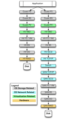
If we look at DAS versus SAN and trace the path data takes when written by an application running “in the cloud,” it would look something like this figure:
 DAS vs. San data path. Click to enlarge.
(A quick aside: Please note that I have left out all kinds of components, such as disk drive firmware, RAID controller firmware, complexities in networking/switching, and the like. All of these would count here as components.)
A piece of data written by the application running inside of the guest operating system (OS) of a virtual server flows as follows with DAS in place:
-
The guest OS filesystem (FS) software accepts a request to write a block of data.
-
The guest OS writes it to its “disk,” which is actually a virtual disk drive using the “block stack” (BS) [1] in its kernel.
-
The guest OS has a para-virtualization (PV) disk driver [2] that knows how to write the block of data directly to the virtual disk drive, which in this case is provided by the hypervisor.
-
The block is passed by the PV disk driver not to an actual disk drive but to the hypervisor’s (HV) virtual block driver (VBD), which is emulating a disk drive for the guest OS.
- At this point we have passed from the “virtualization” layer into the “physical” or real world.
-
Repeating the process for the hypervisor OS, we now write the block to the filesystem (FS) or possibly volume manager (VM), depending on how your virtualization was configured.
-
Again, the block stack handles requests to write the block.
-
A disk driver (DD) writes the data to an actual disk.
-
The block is passed to a RAID controller to be written.
Obviously, laid out like this, the entire task already seems somewhat complex, but this is modern computing with many layers and abstractions. Even with DAS, if something went wrong, there are many places we might need to look to troubleshoot the issue — roughly eight, though the steps I listed are an approximation for the purpose of this article.
SAN increases the complexity significantly, where starting at step 7, we take a completely different route:
-
Instead of writing to the disk driver (DD), in a SAN system we write a network-based block device: the “iSCSI stack,” [3] which provides SCSI [4] commands over TCP/IP.
-
The iSCSI stack then sends the block to the hypervisor’s TCP/IP stack to send it over the network.
-
The block is now sent “across the wire,” itself a somewhat complicated process that might involve things like packet fragmentation and MTU issues, TCP window size issues/adjustments, and more — all thankfully left out here in order to keep things simple.
-
Now, at the SAN storage system, the TCP/IP stack receives the block of data.
-
The block is handed off to the iSCSI stack for processing.
-
The SAN filesystem and/or volume manager determines where to write the data.
-
The block is passed to the block stack.
-
The block is passed to the disk driver to write out.
-
The hardware RAID writes the actual data to disk.
In all, adding the SAN conservatively doubles the number of steps and moving parts involved. Each step or piece of software may be a cause of failure. Problems with tuning or performance may arise because of interactions between any two components. Problems with one component may spark issues with another. To complicate matters, troubleshooting the issues may be complex, in that the guest OS might be Windows, the hypervisor could be Linux, and the SAN might be some other OS all together. All with different filesystems, block stacks, iSCSI software, and TCP/IP stacks.
Complexity isn’t linear
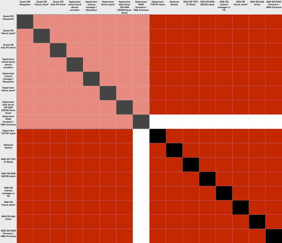
The problem, however, is not so much that there are more pieces, but that those pieces all potentially interact with each other and can cause issues. The problem is multiplicative. There are twice as many parts (or more) in a SAN, but that creates four times as many potential interactions, each of which could be a failure. The following figure shows all the steps as both rows and columns. Interactions could theoretically occur between each two of the steps. (I’ve blacked out the squares where a component intersects with itself because that’s not an interaction between different components.)
This diagram is a matrix of the combinations, where we assume that the hypervisor RAID in my example above isn’t part of the SAN solution. The lighter-colored quadrant in the upper left is the number of potential interactions or failure points for DAS, and the entire diagram depicts those for SAN. Put more in math terms, there are N * (N-1) possible interactions/failures. With this DAS example, that means there are 8 * (8-1) or 56. For the SAN, it’s 240 (16 * (16-1)) minus the hypervisor RAID (16) for 224 — exactly four times as many potential areas of problems or interactions that may cause failures.
How things fail and how uptime calculations work
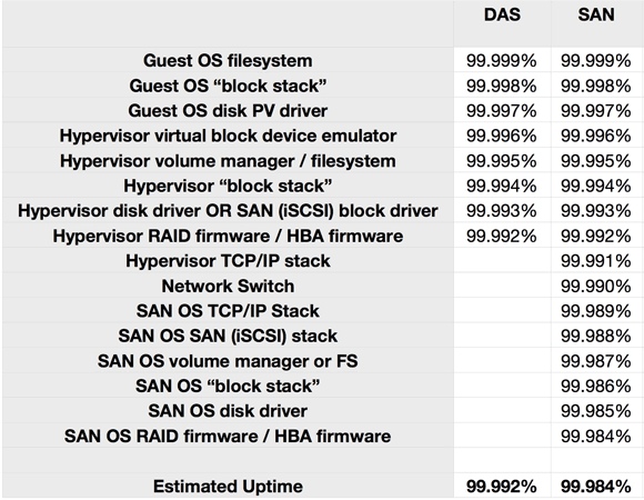
To be certain, each of these components and interactions have varying chances of failure. Some are less likely to fail than others. The problem is that calculating your likely uptime is just like the matrix. It’s a multiplicative effect, not additive. If you want to predict the average uptime of a 99% uptime system with two components, it’s 99% * 99% = 98% uptime.
If every component of our DAS or SAN system is rated for “five 9s” (99.999%) uptime, our calculation is as follows:
The point here is not that DAS is “four 9s” or SAN is “five 9s,” but that by adding more components, we have actually reduced our likely uptime. Simpler solutions are more robust because there are fewer pieces to fail. We have lost a full “9” by doubling the number of components in the system.
An anecdote may bring this home. Very recently, we were visited by a potential customer who described a storage issue. They had moved from a DAS solution to a SAN solution from a major enterprise vendor. Two months after this transition, they had a catastrophic failure. The SAN failed hard for three days, bringing down their entire cloud. A “five nine” enterprise solution actually provided “two nines” that year. In fact, if you tracked uptime across year boundaries (most don’t), this system would have to run without a single failure for 10-plus years to come even close to what most consider a high uptime rating.
It’s worth noting here that another advantage of a DAS system is smaller “failure domains.” In other words, a DAS system failure affects only the local server, not a huge swath of servers as happened with my anecdote above. This is a topic I plan to cover in detail in future articles, as it’s an area that I think is also not well understood.
Large-scale cloud operators are the new leaders in uptime
Once upon a time, we all looked to the telephone system as an example of a “high uptime” system. You picked up the phone, got a dial tone, and completed your call. Nowadays, though, as the complexity of networks has increased while moving to a wireless medium, carrier uptimes for wireless networks have gone down. As data volumes increase, carrier uptimes have been impacted even further.
The new leaders in uptime and availability are the world’s biggest Internet and cloud operators: Google, Facebook, Amazon, eBay, and even Microsoft. Google regularly sees four nines of uptime globally while running one of the world’s largest networks, the largest plant of compute capability ever, and some of the largest datacenters in the world. This is not a fluke. It’s because Google and other large clouds run simple systems. These companies have reduced complexity in every dimension in order to scale up. This higher availability also comes while moving away from or eliminating complex enterprise solutions, running datacenters at extreme temperatures, and otherwise playing by new rules.
Wrapping up
What have we learned here? Simple scales. What this means for businesses is that IT systems stay up longer, have better resiliency in the face of failures, cost less to maintain and run, and are just plain better when simplified. Buying a bigger, more complex solution from an enterprise vendor is quite often a way to reduce your uptime. This isn’t to say that this approach is always wrong. There are times when complex solutions make sense, but stacking them together creates a multiplicative effect. Systems that are simple throughout work best. Lots of simple solutions with some complexity can also work. Lots of complex solutions means lots of failures, lots of operational overhead, and low uptime.
Keep it simple because simple scales while complexity fails.
[1] A “block stack” is a term I use in this article to represent the piece of kernel software that manages block devices. It’s similar in concept to the “TCP/IP stack” used to manage the network for a modern operating system. There is no standard name for the “block stack” as there is for the networking software stack.
[2] Para-virtualization drivers are a requirement in all hardware virtualization systems that allow for higher performance disk and network I/O. They look like a standard operating system driver for a disk, but understand how to talk to the hypervisor in such a way as to increase performance.
[3] In this case, I use iSCSI as the SAN, but AoE, FC, or FCoE are all similar in nature.
[4] The observant reader will note that at the guest layer, we might be writing to a virtual SATA disk, then using SCSI commands over TCP/IP, and finally writing via SCSI or SATA. Each of these protocols potentially has its own issues and tuning requirements. For simplicity, I’ve left the details of the challenges there out of these examples.

